Optical loss after fiber installation is a common concern in FTTH, OSP, and outdoor fiber networks.
Understanding the causes of optical loss after fiber installation helps engineering teams troubleshoot attenuation problems more efficiently.In many cases, the issue is not caused by defective fiber. Instead, it results from installation-related factors such as bending, mechanical stress, connector contamination, splice quality, or hardware mismatch.
Understanding these field-related causes helps engineering teams identify problems faster, reduce troubleshooting time, and improve long-term network reliability.
Common Causes of Increased Optical Loss After Installation
Insertion loss after installation is typically related to one or more of the following Higher optical loss after installation is commonly associated with one or more of the following factors:
- Excessive pulling tension during installation
- Tight routing and small bend radius
- Cable compression at fixation points
- Poor fusion splice quality
- Contaminated connectors
- Improper cable management
- Incompatible clamps or installation hardware
Many of these issues are not immediately visible but can significantly affect network performance.
Fiber Strain Caused by Excessive Installation Tension
Applying excessive pulling force during cable installation can introduce mechanical strain into the fiber.
Although the link may initially pass testing, excessive tension can increase attenuation and reduce long-term stability.
This risk is particularly relevant during aerial deployments, duct installations, and long pulling sections where installation force is not properly controlled.
Good Practice
- Follow the cable manufacturer’s installation recommendations
- Avoid sudden pulling force changes
- Use appropriate installation equipment
- Protect the cable at corners and entry points
- Prevent unnecessary tension during routing
Proper tension control helps maintain optical performance and reduce future maintenance issues.
Macrobending Loss from Tight Routing
One of the most common installation-related causes of optical loss is macrobending.
Macrobending occurs when the cable is visibly bent beyond its recommended bend radius, allowing part of the optical signal to escape from the fiber core.
Typical locations include:
- Building entry points
- Distribution boxes
- Fiber closures
- Slack storage loops
- Indoor routing corners
Loss caused by macrobending is often more noticeable at longer wavelengths such as 1550 nm.
Using bend-insensitive fiber can improve tolerance, but proper routing remains essential.
Microbending Caused by Compression and Localized Stress
Microbending is usually associated with localized mechanical pressure rather than visible cable bends.
Common causes include:
- Over-tightened cable ties
- Excessive clamp pressure
- Cable compression inside closures
- Poor cable support
- Improper hardware selection
Because these stress points may not be visible from the outside, they can be difficult to identify during troubleshooting.
Selecting compatible hardware and avoiding excessive compression helps reduce this type of attenuation.
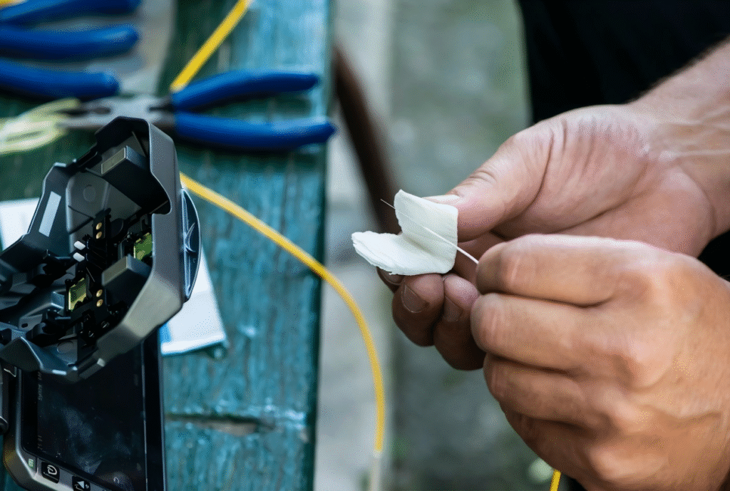
Connector Contamination and Inspection Issues
Not all optical loss increases originate from the cable itself.
Contaminated connector end faces remain one of the most common causes of unexpected loss measurements.
Common issues include:
- Dust contamination
- Oil residue
- Improper cleaning procedures
- Damaged connector ferrules
- Connector mating problems
For this reason, connector inspection and cleaning should always be performed before assuming a cable-related problem.
A simple cleaning procedure can often eliminate unnecessary troubleshooting.
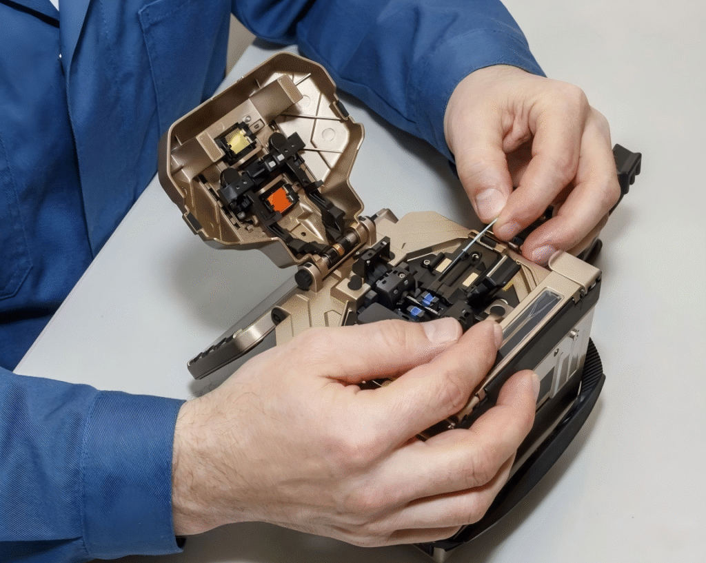
Fusion Splice Quality
Poor splice quality can also increase optical loss after installation.
Potential causes include:
- Fiber misalignment
- Improper cleaving
- Contaminated fiber ends
- Incorrect splice settings
- Insufficient splice protection
Verifying splice quality during installation helps avoid future service issues and reduces the need for repeat visits.
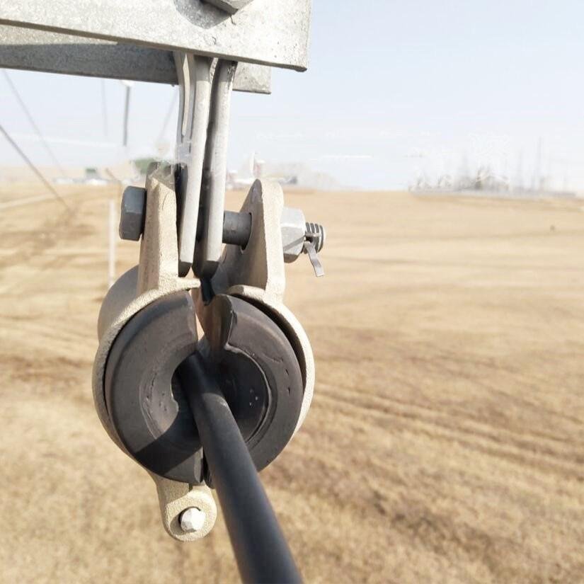
Hardware Compatibility Matters
- Installation hardware plays a larger role in optical performance than many people expect.
- In aerial deployments, suspension clamps, tension clamps, and support accessories must match the cable structure and diameter.
- Incorrect hardware selection may introduce:
- Excessive compression
- Uneven loading
- Localized stress
- Long-term attenuation increases
- Cable and hardware should always be considered as a complete installation system rather than independent components.
Why Higher Loss at 1550 nm Often Indicates Installation Stress
A common field observation is that optical loss becomes more noticeable at 1550 nm than at 1310 nm.
When this occurs, engineers often investigate:
- Tight bends
- Routing problems
- Compression points
- Installation stress
This does not automatically mean the fiber is defective.
In many cases, it indicates that installation conditions should be reviewed before replacing any components.
A Common Engineering Question Should the Cable Be Replaced First?
Not necessarily.
When optical loss increases after installation, replacing the cable is often not the first step.
Experienced engineers usually begin by checking:
- Connector cleanliness
- Splice quality
- Bend radius
- Hardware compatibility
- Cable routing
- Mechanical stress points
Many attenuation issues can be resolved without replacing the cable itself.
Practical Recommendations
To minimize optical loss after installation:
- Control installation tension
- Maintain proper bend radius
- Avoid excessive cable compression
- Use compatible clamps and accessories
- Inspect and clean connectors before testing
- Verify splice quality
- Manage cable routing carefully
- Protect the cable at entry points and closures
These practices help maintain stable optical performance throughout the network lifecycle
Key Takeaways
- Increased optical loss after installation is often related to installation conditions rather than defective fiber.
- Excessive tension may introduce fiber strain. Tight routing can cause macrobending loss.
- Compression and localized pressure may contribute to microbending-related attenuation.
- Connector contamination and poor splice quality remain common field issues.
- Proper cable handling and compatible hardware improve long-term network reliability.
Frequently Asked Questions
Why does optical loss increase after fiber installation?
The most common causes include excessive tension, tight routing, connector contamination, splice issues, and mechanical stress introduced during installation.
Is higher loss at 1550nm normal?
Loss at 1550 nm is often more sensitive to bending and installation-related stress. Engineers typically investigate routing and mechanical conditions when this occurs.
Can installation hardware affect optical performance?
Yes. Improperly matched clamps, supports, or accessories may introduce compression and localized stress that increase attenuation.
Should connectors be cleaned before optical testing?
Absolutely. Connector contamination is one of the most common causes of inaccurate loss measurements and should always be checked before further troubleshooting.
What causes optical loss after fiber installation?
Optical loss after fiber installation is commonly caused by bending, mechanical stress, connector contamination, splice quality issues, or improper hardware selection.
Need Help Evaluating Installation-Related Loss?
Optical loss issues are not always caused by cable defects.
If you are troubleshooting attenuation after installation, our team can help review the deployment scenario, cable routing, and hardware configuration to identify possible causes.