
ADSS Fiber Cable (All-Dielectric Self-Supporting) is designed for aerial fiber optic deployment without requiring a separate messenger wire.
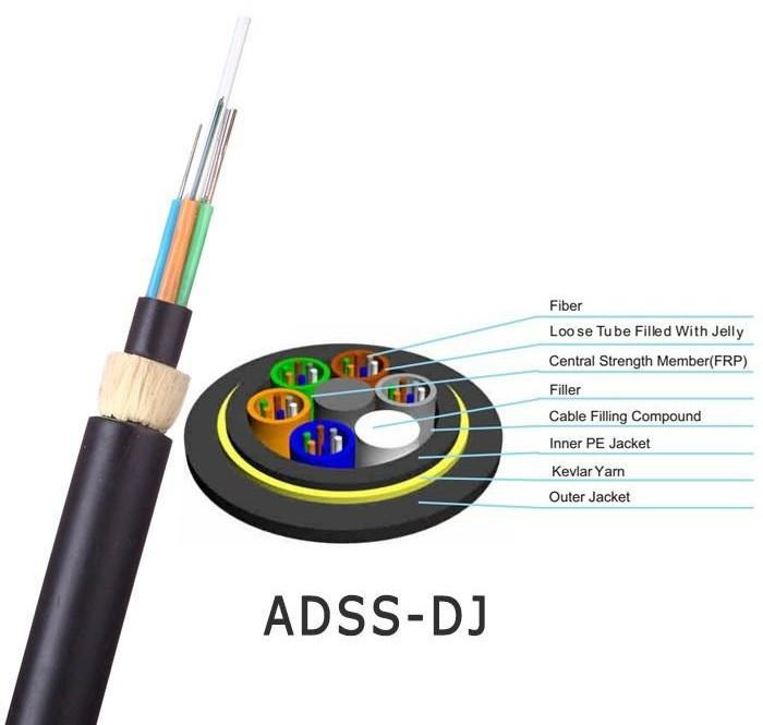
The cable supports its own mechanical load through distributed aramid yarn strength members, making it suitable for utility poles, ISP backbone networks, rural broadband projects, highway communication routes, and power utility communication systems.
Unlike messenger-supported cable systems, ADSS can be installed directly between poles while maintaining a fully dielectric structure.
Because aerial environments vary significantly, successful ADSS deployment depends not only on fiber count, but also on span length, wind exposure, pole conditions, hardware selection, and long-term environmental loading.
Why ADSS Cable Is Widely Used
ADSS offers several advantages for aerial OSP networks:
✅ No messenger wire required
✅ Fully dielectric construction
✅ Lightweight installation
✅ Suitable for utility pole sharing
✅ Compatible with rural and backbone deployments
✅ Lower installation complexity compared with messenger-supported systems
Common applications include:
- ISP backbone expansion
- Rural broadband projects
- Utility communication networks
- Highway communication systems
- Smart grid infrastructure
- Municipal fiber networks
Typical ADSS Deployment Scenarios
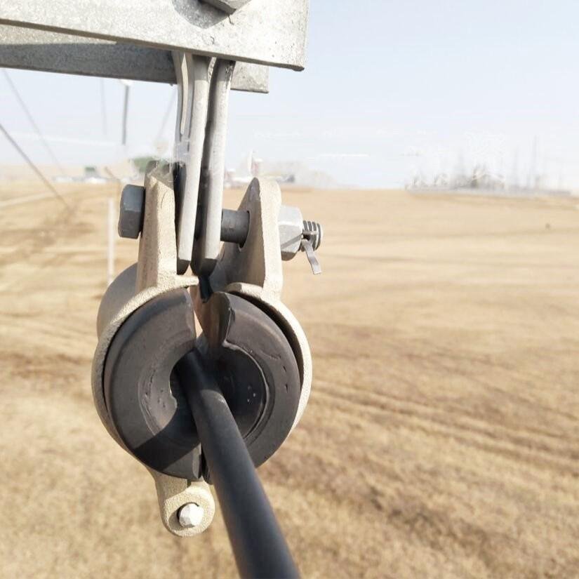
Rural Broadband Networks
Large pole-to-pole distances and limited infrastructure often make ADSS a practical solution.
Utility Pole Sharing
ADSS is frequently used where communication networks share infrastructure with electrical distribution routes.
Highway Communication Routes
Long roadside deployments often benefit from self-supporting cable structures.
Mountainous Areas
Aerial deployment may reduce civil construction costs compared with underground routes.
ADSS Structure Overview
A typical ADSS cable may include:
- Optical fibers
- PBT loose tubes
- Water-blocking materials
- Filling elements
- Aramid yarn strength members
- HDPE outer sheath
- Optional Anti-Tracking (AT) sheath
- Optional rodent-resistant sheath
Actual cable structures vary according to span requirements and environmental conditions.s later due to accumulated environmental stress.
ADSS Span Selection Guide
One of the most common mistakes is selecting ADSS based only on fiber count.
Span length often has a much greater impact on cable design.
| Typical Span | Common Design Approach |
|---|---|
| Up to 80m | Mini ADSS |
| 80–150m | Standard ADSS |
| 150–300m | Reinforced ADSS |
| Above 300m | Project-specific engineering review |
Span selection should also consider:
- Wind loading
- Temperature variation
- Pole height
- Sag requirements
- Terrain conditions
- Future expansion
Environmental Selection Guide
The same ADSS cable may not be suitable for every environment.
High UV Exposure
For tropical and high-sunlight regions, UV-resistant HDPE sheaths help improve long-term durability.
Rodent-Prone Areas
In agricultural and rural environments, optional rodent-resistant designs such as Nylon 12 sheaths may improve protection against animal damage.
Utility Corridors
For installations near medium- or high-voltage infrastructure, Anti-Tracking (AT) sheath designs may be recommended depending on electrical field conditions.
Coastal Environments
Additional weather-resistant materials may help improve long-term performance in humid or salt-exposed environments.
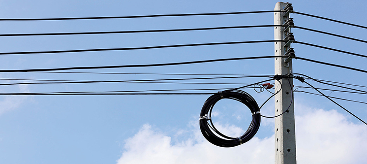
What Causes ADSS Failures in the Field?
In real projects, installation quality often affects cable lifespan more than people In many projects, the fiber itself is not the problem.
Failures often originate from installation and environmental factors.
Common examples include:
- Incorrect span design
- Excessive installation tension
- Poor sag adjustment
- Vibration exposure
- Improper hardware selection
- UV aging
- Environmental loading
Many networks pass initial OTDR testing but develop problems later as mechanical stress accumulates over time.
Common ADSS Selection Mistakes
Choosing Cable Only by Price
Lower-cost designs may not match the actual route conditions.
Ignoring Span Conditions
Fiber count does not determine aerial performance.
Mechanical loading does.
Underestimating Wind Exposure
Wind-induced vibration can significantly affect long-term stability.
Using Incompatible Hardware
Incorrect suspension or dead-end hardware may create concentrated stress points.
Ignoring Future Environmental Conditions
Temperature variation, vegetation growth, and route changes should be considered during design.
but to maintain long-term network stability after deployment.
Long-Term Reliability Factors
Several factors influence ADSS service life:
- Span length
- Cable weight
- Installation tension
- Sag control
- Wind exposure
- UV exposure
- Hardware compatibility
- Environmental conditions
Long-term stability is often determined by the interaction of these factors rather than by cable specifications alone.
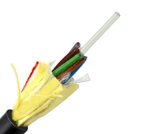
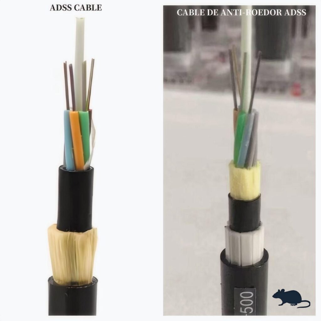
Typical ADSS Cable Structure
A standard ADSS cable typically includes:
- FRP central strength member
- Loose tubes with optical fibers
- Water blocking elements
- Aramid yarn strength layer
- HDPE outer sheath
This fully dielectric structure allows installation near power distribution routes without electrical conductivity risks.
Depending on the project, different sheath materials and aramid designs may be selected according to span and environmental conditions.
Recommended ADSS Configuration by Span
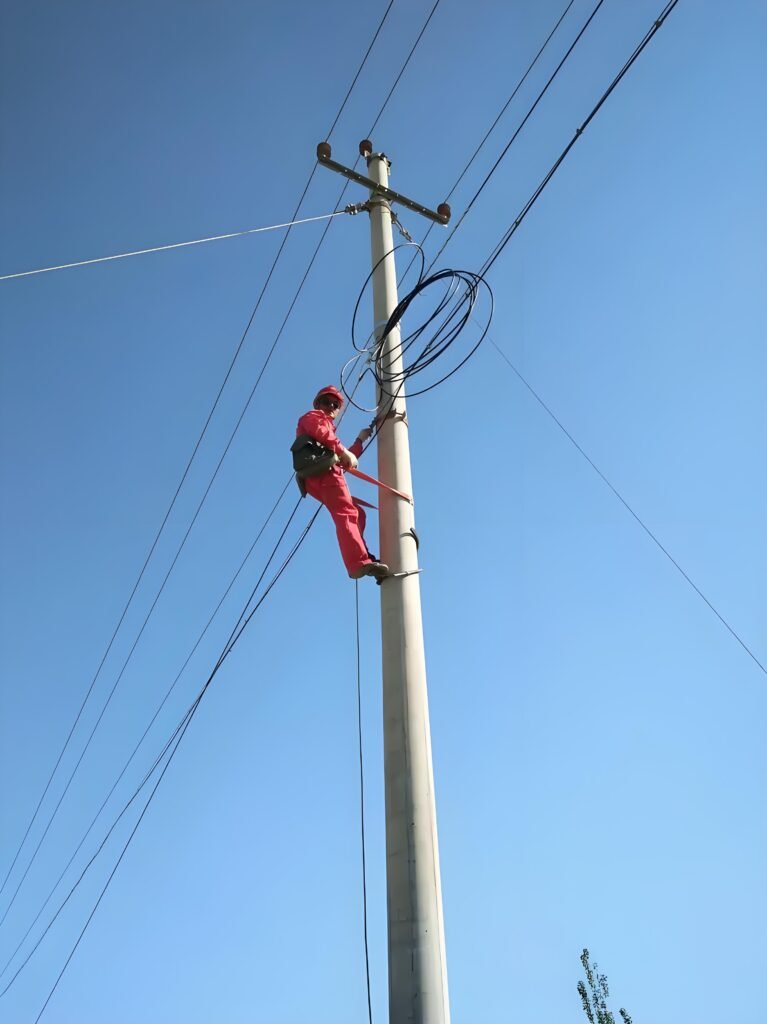
ADSS cable design is usually influenced by span length, but span alone should never be the only selection factor.
Wind exposure, terrain, pole conditions, temperature variation, and hardware compatibility must also be considered.
The following table provides a general engineering reference.
| Typical Span | Common ADSS Design | Typical Applications |
|---|---|---|
| Up to 80m | Mini ADSS | Urban access networks, FTTH feeder routes, short distribution links |
| 80–150m | Standard ADSS | ISP backbone expansion, rural broadband deployment |
| 150–300m | Reinforced ADSS | Utility communication routes, long rural aerial spans |
| Above 300m | Project-specific design review recommended | High-load environments, complex terrain, utility infrastructure |
Important:
Actual cable selection should also consider:
- Wind loading
- Sag requirements
- Pole strength
- Terrain profile
- Temperature variation
- Long-term environmental exposure
A 100m span in a calm urban environment may require a completely different cable design than a 100m span exposed to strong wind, mountainous terrain, or utility corridor conditions.
Not Sure Which ADSS Design Fits Your Route?
Share the following information:
- Maximum span length
- Pole type
- Wind conditions
- Installation environment
- Fiber count
Our engineering team can help review the route and suggest a suitable ADSS configuration.
Frequently Asked Questions
What span can ADSS cable support?
ADSS designs are available for spans ranging from short distribution routes to several hundred meters depending on cable construction and environmental conditions.
Can ADSS cables be installed near power lines?
Yes. Because ADSS is fully dielectric, it is commonly used along utility routes.
However, installations near higher-voltage infrastructure may require additional engineering evaluation and specialized sheath options.
Is heavier ADSS cable always better?
No.
Cable weight, span length, wind load, and pole conditions should be balanced together.
Can incorrect hardware damage ADSS cable?
Yes.
Improper hardware selection may create localized stress that affects long-term cable performance
Why do some ADSS problems appear months later?
Many aerial network issues develop gradually due to vibration, environmental exposure, mechanical loading, and installation conditions.
Related Resources
- How to Install ADSS Cable on Utility Poles
- ADSS vs Messenger-Supported Cable
- How to Select Fiber Cable for Aerial Span Deployment
- Common Causes of Optical Loss After Installation
Discuss Your Deployment Scenario
Every aerial route is different.
Before selecting an ADSS cable, it is helpful to know:
- Maximum span length
- Pole type
- Wind conditions
- Voltage environment
- Terrain profile
- Fiber count
- Installation method
Our engineering team can review your deployment scenario and suggest a suitable ADSS cable configuration based on actual field conditions.