ADSS fiber cable installation is one of the most important stages in aerial fiber network deployment.
It is commonly used in:
- rural broadband networks
- power utility communication routes
- backbone aerial fiber networks
- long-span distribution systems
However, many ADSS network problems are not caused by the fiber itself.
In many cases, failures originate from:
- incorrect span planning
- excessive installation tension
- poor sag adjustment
- vibration stress
- improper hardware selection
- environmental exposure
The network may initially pass testing and operate normally.
But months later, mechanical stress gradually affects long-term stability.
Proper installation practices are critical to reduce future maintenance problems.
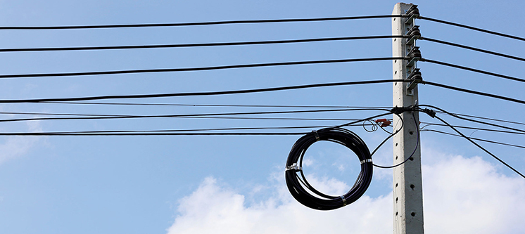
Typical ADSS Pole Installation Structure
A standard ADSS aerial deployment usually includes:
- utility poles
- suspension clamps
- dead-end tension hardware
- vibration dampers
- splice closures
- aerial span sections
Unlike figure-8 cable, ADSS is fully dielectric and self-supporting, which makes it suitable for installation near power distribution infrastructure.
However, installation near power lines still requires proper clearance and environmental evaluation.
Step 1 – Span Assessment and Route Evaluation
Before installation, one of the most important tasks is evaluating the actual route conditions.
Typical factors include:
- span length
- terrain elevation differences
- wind conditions
- pole height
- road crossing clearance
- future sag conditions
- environmental exposure
In long aerial spans, mechanical calculations become increasingly important.
ADSS cable selection is normally related to:
- RTS (Rated Tensile Strength)
- MAT (Maximum Allowable Tension)
- expected environmental load
In many installations, long-term working tension is commonly designed below a percentage of RTS to reduce long-term fiber strain.
Why Span Design Matters
Incorrect span design is one of the most common causes of long-term ADSS instability.
If the span exceeds the intended design conditions, problems may gradually appear such as:
- excessive sag
- vibration
- hardware stress
- attenuation drift
- premature jacket aging
In high-wind environments, incorrect sag adjustment may also increase aeolian vibration around suspension points.
Many of these problems appear months after installation rather than during commissioning.
Mechanical performance evaluation methods for optical fiber cables are commonly referenced in IEC 60794 standards, including tests related to tensile load, environmental durability, and mechanical performance.
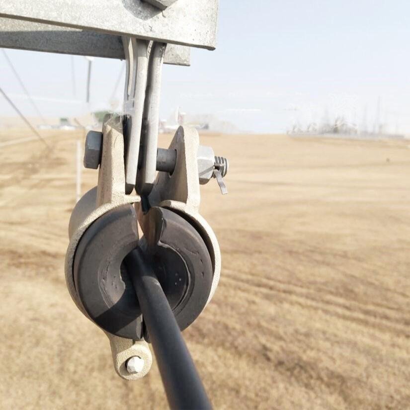
Step 2 – Hardware Selection and Pole Inspection
Before pulling the cable, hardware compatibility should be verified.
Typical components include:
- suspension clamps
- dead-end tension sets
- preformed armor rods
- vibration dampers
- pole brackets
Pole conditions should also be inspected:
- structural stability
- pole alignment
- corrosion
- clearance conditions
- vegetation exposure
Improper hardware selection may create concentrated stress points that gradually damage the cable jacket or internal structure.
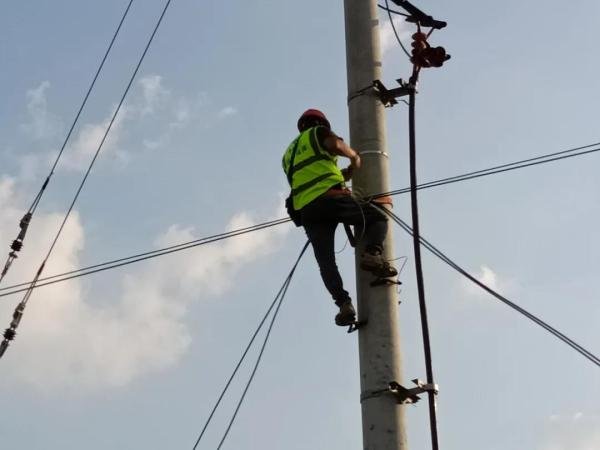
Step 3 – Controlled Cable Pulling
During installation, cable tension and bending conditions should be carefully controlled.
Typical installation practices include:
- using cable rollers
- avoiding cable twisting
- controlling pulling tension
- maintaining recommended bending radius
- protecting the cable near hardware points
Dynamic bending radius during installation is commonly maintained above a multiple of the cable diameter to reduce microbending risk.
Excessive pulling tension may create residual strain inside the cable structure.
Initially, OTDR results may appear normal.
However, attenuation may gradually increase later under long-term environmental stress.
Step 4 – Sag Adjustment
After cable pulling, sag adjustment becomes critical for long-term mechanical stability.
Proper sag helps:
- distribute tension evenly
- reduce vibration stress
- maintain ground clearance
- improve long-span stability
Incorrect sag conditions may create two different problems:
Sag too small
- excessive mechanical tension
- higher long-term strain
- vibration concentration near hardware
Sag too large
- insufficient ground clearance
- increased cable movement
- higher environmental exposure
In many rural aerial routes, improper sag adjustment becomes visible only after seasonal temperature or wind changes.
Step 5 – Vibration Protection and Final Inspection
In long spans or windy environments, vibration protection may be necessary.
Continuous wind exposure may gradually create:
- aeolian vibration
- hardware fatigue
- jacket wear
- long-term attenuation instability
For this reason, some long-span installations use vibration dampers near suspension points.
Final inspection normally includes:
- hardware verification
- sag inspection
- cable routing confirmation
- clearance validation
- visual jacket inspection
Common Installation Mistakes
Typical field problems include:
- installing beyond designed span
- excessive pulling force
- sharp bending near hardware
- incorrect clamp selection
- insufficient sag allowance
- poor cable routing
- inadequate vibration protection
Many of these issues do not cause immediate failure.
Instead, environmental stress gradually affects the cable over time.
How to Select Fiber Cable for Aerial Deployment
Environmental Conditions Matter
Outdoor ADSS installations are strongly affected by environmental conditions such as:
- wind vibration
- UV exposure
- temperature cycling
- humidity
- ice loading
- vegetation exposure
In tropical environments, long-term UV exposure may accelerate jacket aging if the cable structure is not designed for outdoor environmental conditions.
In rural environments, animal activity or vegetation contact may also increase maintenance risk
ADSS Installation Near Power Lines
ADSS cable is dielectric and widely used along power utility routes.
However, installation near high-voltage lines still requires proper engineering evaluation.
Factors may include:
- electrical environment
- clearance distance
- induced electrical effects
- tracking-resistant jacket requirements
In some high-voltage environments, specialized jacket designs may be considered to improve long-term durability.
Why Many ADSS Problems Appear Later
One common situation in aerial networks is:
Installation completed
↓
Initial OTDR test passed
↓
Months of wind and temperature exposure
↓
Gradual mechanical stress accumulation
↓
Vibration near hardware
↓
Attenuation instability
↓
Maintenance intervention
This is why long-term ADSS reliability depends not only on installation speed, but also on correct mechanical design and environmental adaptation.
Key Takeaways
– Proper span planning reduces long-term mechanical stress.
– Hardware compatibility directly affects cable reliability.
– Correct sag adjustment improves network stability.
– Environmental conditions influence long-term performance.
– ADSS fiber cable installation should always consider route conditions, wind exposure, and maintenance requirements.
FAQ
What span can ADSS cable support?
ADSS cable can be designed for spans from approximately 50m to over 500m depending on RTS, environmental load and installation conditions.
Are vibration dampers necessary?
They are commonly considered in long-span or high-wind installations to reduce long-term vibration stress.
Can ADSS cable be installed near power lines?
Yes.
However, installations near high-voltage infrastructure still require proper clearance and environmental evaluation.
Why do some ADSS failures appear months later?
Many aerial problems are cumulative and gradually develop due to mechanical stress, vibration and environmental exposure over time.
Discuss Your ADSS Installation Scenario
Every aerial deployment environment is different.
Factors such as:
- span length
- wind exposure
- terrain
- pole conditions
- temperature variation
- installation tension
- power line environment
may directly affect long-term ADSS performance.
If you are evaluating an aerial fiber deployment, we can help review the installation scenario and suggest suitable ADSS cable structures according to actual field conditions.