
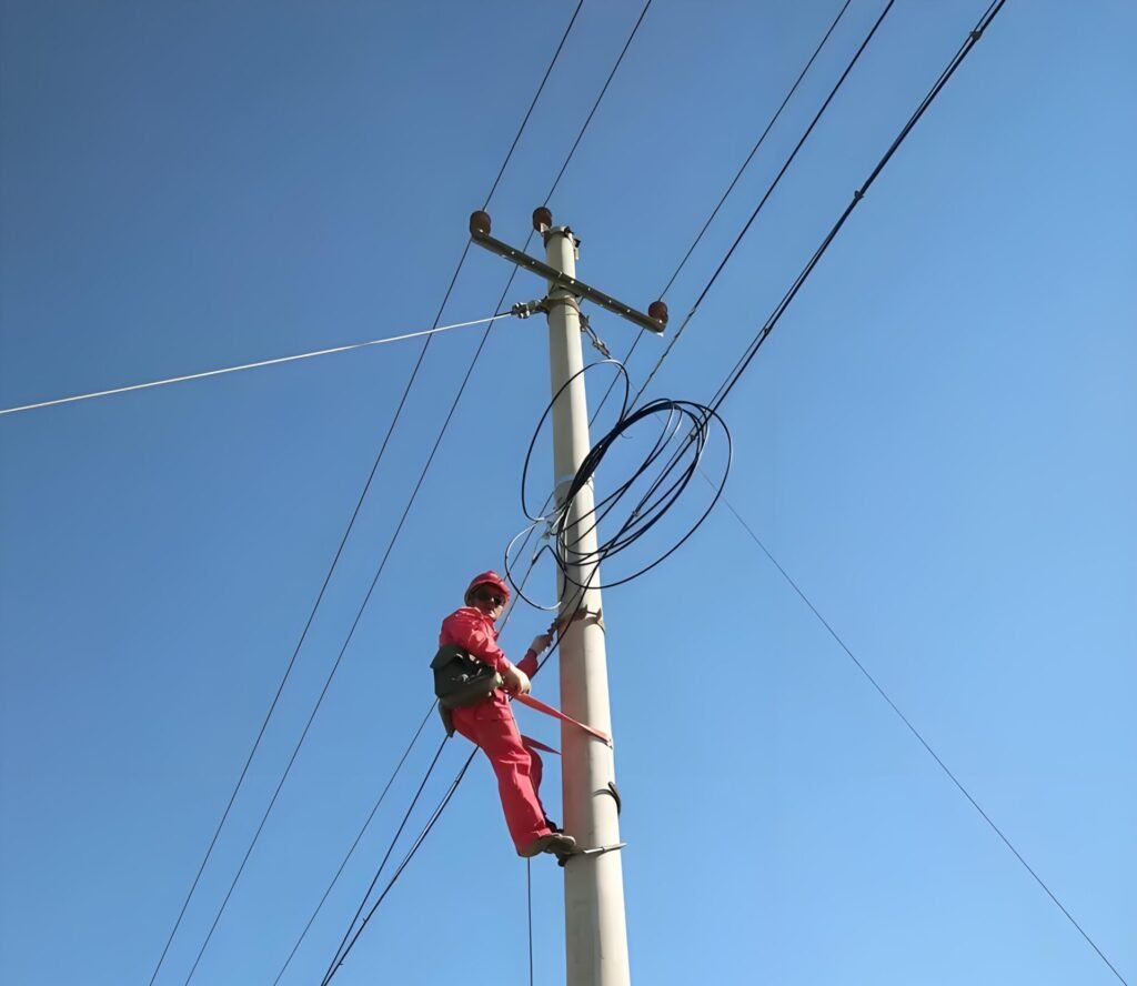
Fiber cable selection for aerial deployment is not determined by span length alone.
Understanding fiber cable selection for aerial deployment helps engineering teams reduce installation risks and improve long-term network reliability.
In real-world OSP projects, cable selection must consider mechanical loading, environmental exposure, installation methods, hardware compatibility, and long-term maintenance requirements.
Two routes may have the same span length but require completely different cable structures.
Understanding these factors helps engineering teams avoid installation problems, reduce maintenance costs, and improve long-term network reliability.
A Common Selection Mistake
One of the most common mistakes in aerial fiber deployment is selecting a cable based only on span length.
For example, two routes may both have 80-meter spans.
One route may be located in a sheltered urban environment with minimal wind exposure.
The other may cross open terrain where strong wind, temperature variation, and uneven loading are common.
Although the span length is identical, the cable requirements may be completely different.
For this reason, experienced engineers evaluate the entire route environment rather than relying on span length alone.
Typical Aerial Deployment Environment
In aerial fiber networks, cables are commonly installed between utility poles, roadside infrastructure, or shared communication routes.
Typical deployments include:
- Urban utility pole networks
- Rural broadband routes
- Utility communication systems
- Industrial facilities
- Campus and community networks
While span lengths often range from short urban distances to longer rural routes, environmental conditions frequently have a greater impact on performance than span length itself.
Important considerations include:
- Wind exposure
- Temperature variation
- Installation tension
- Route profile
- Pole condition
- Existing infrastructure
Why Span Length Alone Is Not Enough
Successful fiber cable selection for aerial deployment requires evaluating the entire route environment rather than relying on span length alone.
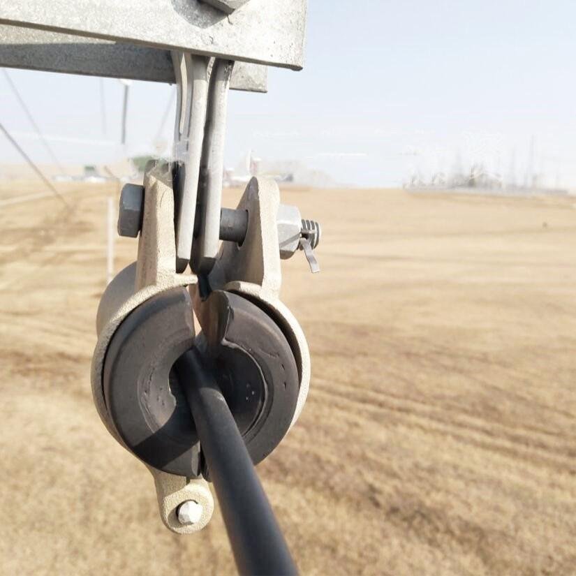
Span length is an important design parameter, but it does not fully represent the mechanical conditions experienced by a cable.
Several additional factors influence long-term performance:
- Installation tension
- Cable weight and sag behavior
- Wind loading
- Hardware compatibility
- Environmental exposure
- Maintenance accessibility
A cable that performs reliably under one set of conditions may experience excessive stress under another, even when span lengths are identical.
Successful aerial deployments are usually the result of matching the cable structure to the overall route conditions rather than a single measurement.
What Engineers Usually Check First
Before selecting a cable, engineers typically evaluate:
- Pole-to-pole distance
- Route profile and terrain
- Existing messenger infrastructure
- Environmental exposure
- Installation method
- Maintenance accessibility
- Utility requirements
These factors often provide more useful information than fiber count or span length alone.
Key Engineering Factors for Cable Selection
To improve long-term performance, engineers usually evaluate the following areas:
Mechanical Strength
The cable must be capable of handling expected loading conditions throughout its service life.
Considerations include:
- Tensile performance
- Span configuration
- Sag behavior
- Environmental loading
Hardware Compatibility
Cable performance depends not only on the cable itself but also on the hardware supporting it.
Suspension clamps, dead-end assemblies, and other accessories should match the cable structure and diameter.
Many installation problems originate from hardware mismatch rather than cable defects.
Environmental Durability
Outdoor fiber cables are exposed to:
- UV radiation
- Wind
- Rain
- Humidity
- Temperature variation
Cable structures should be selected according to the expected operating environment.
Installation Method
The available installation equipment, construction method, and field experience can influence cable selection.
A technically suitable cable may still create problems if installation conditions are not properly considered.
ADSS vs Messenger-Supported Cable
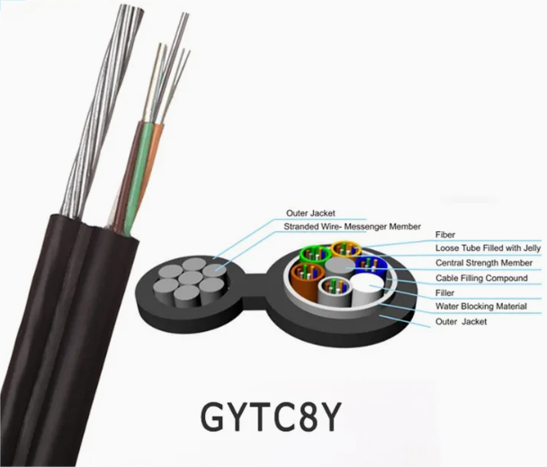
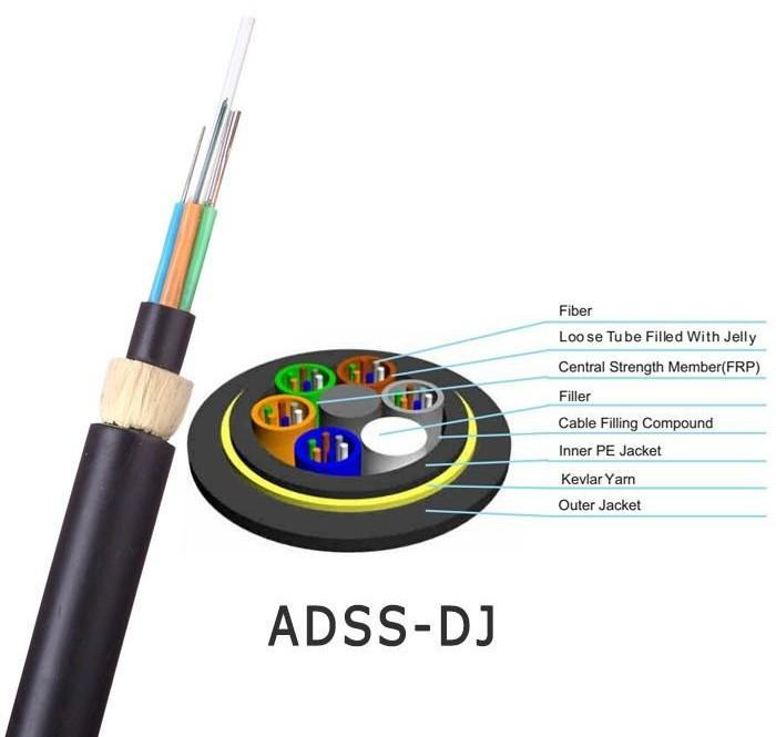
Two common approaches are used for aerial fiber deployment.
ADSS (All-Dielectric Self-Supporting)
ADSS cables carry mechanical load internally through dielectric strength members.
They are often selected when:
- No messenger infrastructure exists
- Electrical isolation is important
- A lightweight solution is preferred
- Installation simplicity is desired
Messenger-Supported Systems
Messenger-supported systems use a steel support strand to carry mechanical load.
They are often selected when:
- Existing messenger infrastructure is available
- Additional mechanical support is preferred
- Long aerial routes are involved
- Installation practices already use messenger systems
The most appropriate solution depends on route conditions rather than a single performance characteristic.
Typical Deployment Scenarios
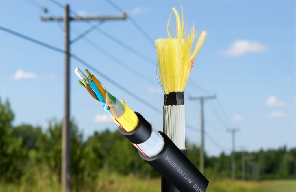
Urban Utility Pole Networks
Urban routes often involve relatively short to medium spans and controlled environmental conditions.
In these situations, ADSS may provide a straightforward deployment solution where messenger infrastructure is unavailable.
Rural Broadband Routes
Rural routes frequently involve longer distances and greater environmental exposure.
Engineers often pay closer attention to cable loading, hardware matching, and long-term maintenance requirements.
Depending on route conditions, both ADSS and messenger-supported systems may be suitable.
Existing Messenger Infrastructure
Where messenger wire is already installed, attaching a fiber cable to the existing support system can reduce installation time and project cost.
This is often one of the most practical upgrade approaches.
Special Considerations for Utility Routes
When aerial fiber cables are installed near utility infrastructure, additional engineering considerations may apply.
Factors such as:
- Electrical field conditions
- Hardware design
- Cable jacket requirements
- Route clearances
may influence cable selection.
Project requirements vary significantly between utility environments, so cable structures should always be evaluated according to local engineering standards and operating conditions.
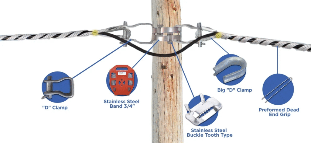
Why Hardware Matching Matters
Even a correctly selected cable can experience long-term performance problems when installation hardware is not properly matched.
Examples include:
- Improper suspension clamp sizing
- Excessive localized pressure
- Incorrect dead-end hardware
- Poor load distribution
In many field cases, installation issues originate from hardware incompatibility rather than the cable itself.
Evaluating cable and hardware as a complete system helps improve long-term reliability.
Practical Field Observation
One common misconception is that the strongest cable is always the best choice.
In practice, successful aerial deployments usually result from selecting a cable structure that matches the installation environment, maintenance strategy, and available infrastructure.
Many long-term performance issues can be traced to mismatched installation conditions rather than cable quality.
For this reason, experienced engineers often focus on route conditions first and product specifications second.
A Question We Often Receive
Many project teams ask:
“Can we use the same cable type on every aerial route?”
In practice, the answer is usually no.
Routes with similar span lengths may experience very different loading conditions, environmental exposure, and installation constraints.
For this reason, cable selection should be based on the overall deployment scenario rather than a single parameter.
Key Takeaways
- Span length is only one factor in aerial cable selection.
- Environmental conditions often influence performance more than span length alone.
- Hardware compatibility is essential for long-term reliability.
- Existing infrastructure frequently affects the most practical cable choice.
- Both ADSS and messenger-supported systems can perform successfully when matched to route conditions.
- System-level evaluation helps reduce installation problems and future maintenance costs.
Frequently Asked Questions
How do I select fiber cable for a 60–80 meter aerial span?
Cable selection should consider installation conditions, environmental exposure, hardware compatibility, and route requirements rather than span length alone.
Is span length the most important factor in aerial cable selection?
No.
Span length is important, but engineers also evaluate loading conditions, environmental exposure, installation methods, and maintenance requirements.
Can two routes with the same span require different cable types?
Yes.
Wind exposure, terrain, infrastructure, and installation methods can result in different cable requirements even when span lengths are identical.
What is the most common cable selection mistake?
Selecting a cable based only on fiber count or span length without evaluating the actual installation environment.
What affects fiber cable selection for aerial deployment?
Fiber cable selection for aerial deployment is influenced by span conditions, environmental exposure, installation methods, hardware compatibility, and long-term maintenance requirements.
Need Help Evaluating an Aerial Deployment?
Every route presents different installation challenges.
If you are planning a rural broadband project, utility communication network, or OSP deployment, our team can help review the installation scenario and discuss suitable cable structures based on actual field conditions.